Load testing your process
TrussLab cannot publish load ratings for parts you manufacture yourself. It can give you a standard fixture to measure your own process.
Why there are no published ratings#
The practical strength of a TrussLab frame is decided by your manufacturing process, not by the geometry alone: the print technology (FDM, SLA, SLS), the material (PLA, PETG, ABS, PA12), how well your printer and environment are dialed in, and, for bonded joints, the adhesive and bonding process. Publishing a single load rating would be wrong for almost everyone.
So instead of ratings, TrussLab provides a canonical test fixture. Build it with your process, load it, and you have a real number for your parts, not ours.
The fixture#
The load test presets are small wall-mounted tripods: three tubes meeting in a printed apex joint, each leg ending in a foot flange. Use Load test - bolted for end-bolted sleeve joints, or Load test - bonded for bonded tube-sleeve joints. Mount the fixture to a wall or a thick OSB plate and hang weight from the apex.
The shape is chosen deliberately. Three members meeting at one loaded point form a statically determinate structure, so the force in each tube follows directly from the geometry. Hanging load also puts the upper member and its joint in tension, the failure mode that actually matters for printed and bonded joints. A result from this fixture tells you what your joints can carry, not just that one particular bracket held.
The preset exposes wallOffset, legsRadius, and tubeRadius, so you can match your stock. Keep in mind that geometry changes the forces: a shallower tripod (larger offset, smaller spread) multiplies the member forces for the same hung weight, so compare numbers only between builds with the same proportions.
Small printed joints, tested to failure#
This bolted reference build uses four full-density PETG joint bodies, six printed internal spacers, three 277 mm aluminium tubes with a 12 mm outer diameter and 1 mm wall, and six M3×12 bolts with matching nuts. The bolts clamp the joint bodies to the internal spacers; the spacers themselves are bonded into the tube ends. The printed parts took 45 minutes and 25 g of filament; the complete fixture weighs 100 g.
- 35 kg highest load held without visible damage
- 37.5 kg failure load
- Bond pull-out observed failure mode
- 100 g complete fixture
- 25 g PETG
- 45 min total print time
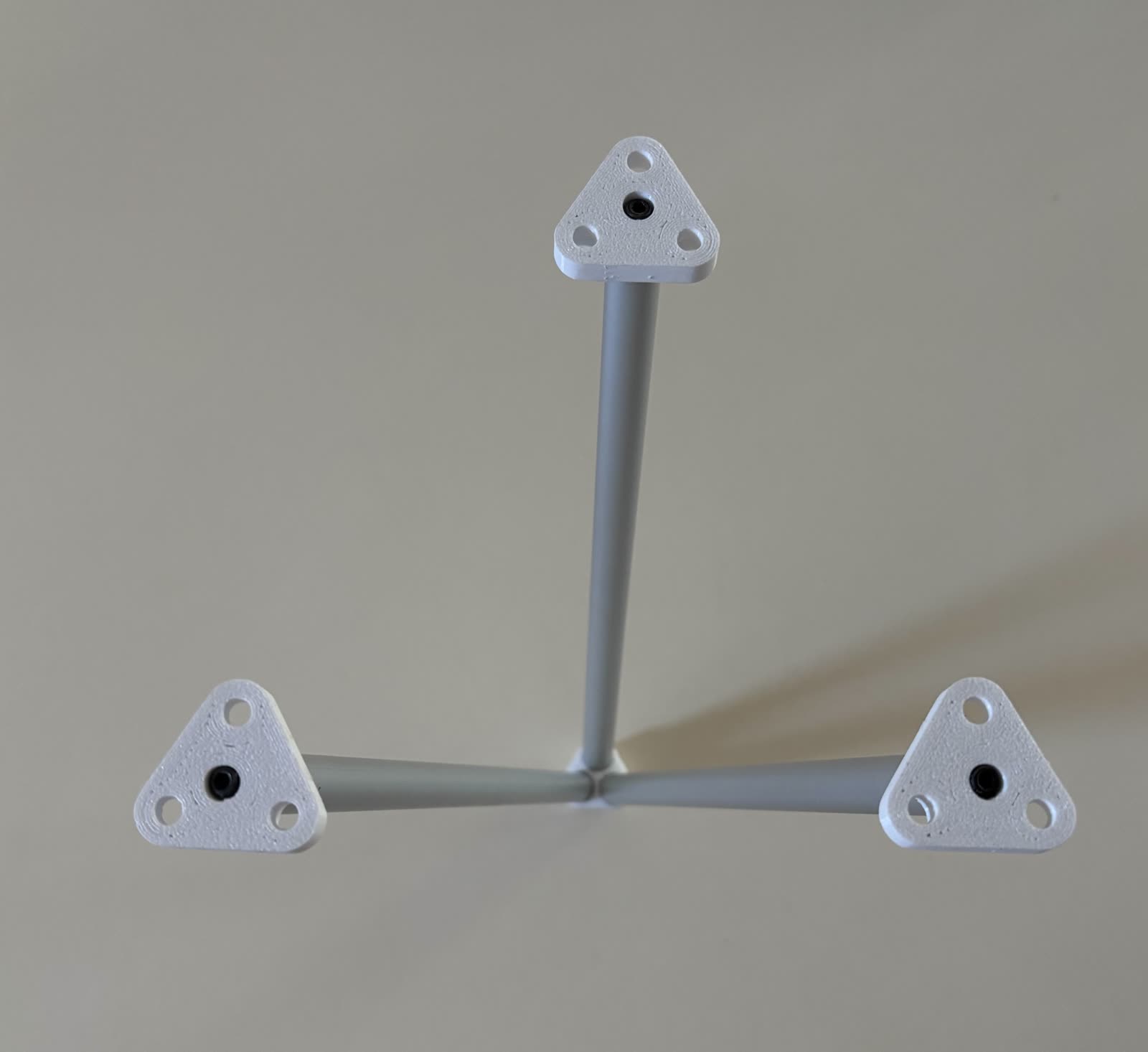
Mounted to an OSB test wall, the fixture was initially loaded with 20 kg and left in place for an informal creep observation. Testing later continued in steps to failure. It supported 35 kg without visible damage.
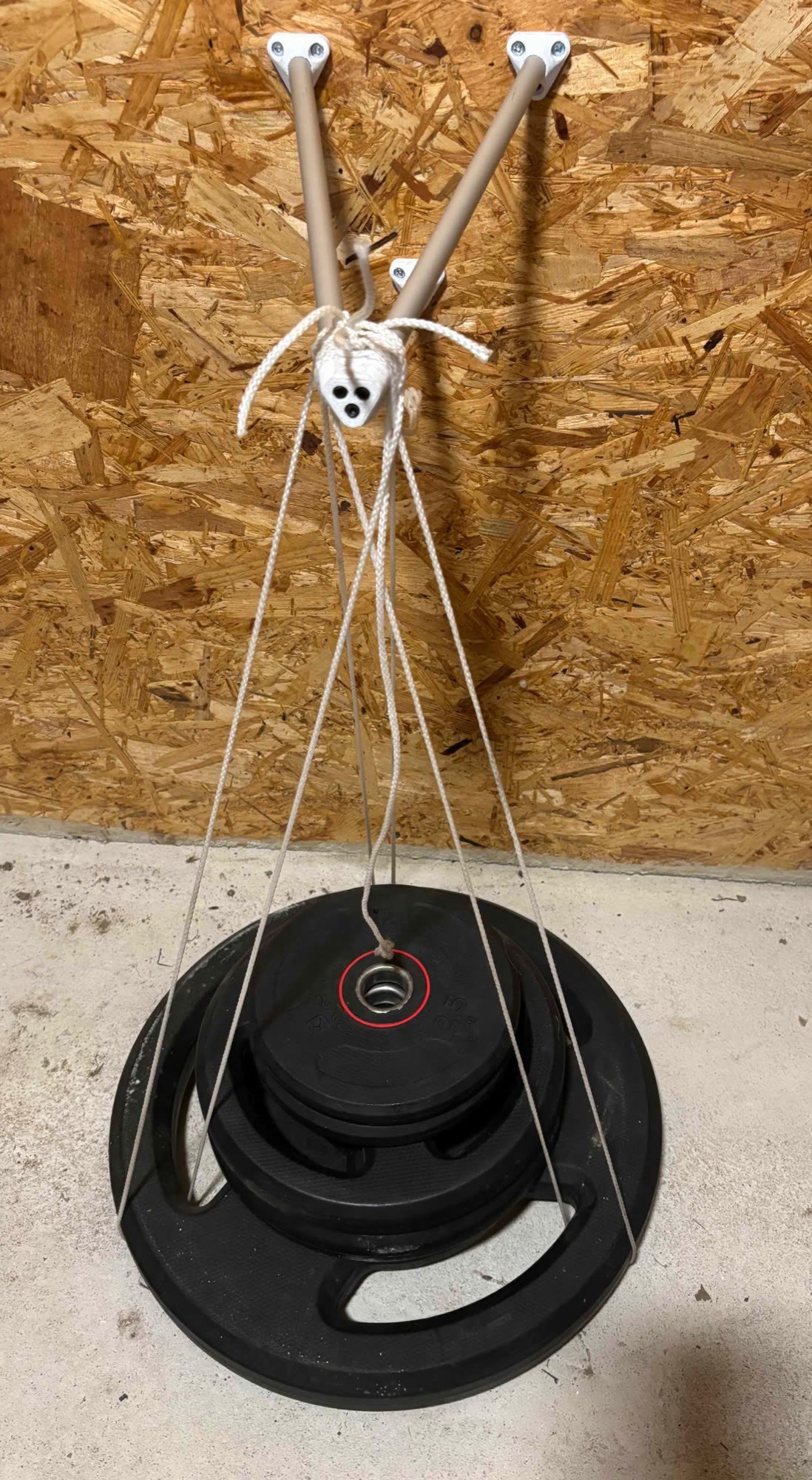
At 37.5 kg, one connection failed when the printed internal spacer carrying the captive nut pulled cleanly out of the aluminium tube. The printed flange, bolt, tube, and wall mounting remained visibly intact; the observed failure was at the bond between the internal spacer and the tube rather than a fracture of the printed joint or metal hardware.
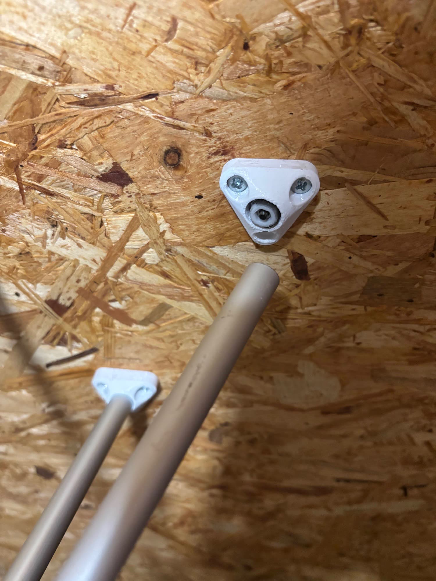
This is a single destructive test, not a certified load rating or a safe working load. Its result belongs to this specific print, adhesive preparation and cure, assembly, geometry, and mounting. The OSB itself flexes, so the setup is not used to report fixture stiffness or deflection. What the test does show is the load path and the limiting interface in this build: the aluminium tubes and printed joints carried the load until the internal spacer-to-tube bond pulled out.
Testing#
Build the fixture exactly as you would build a real frame, with the same printer, material, settings, and assembly process. Mount it into solid material with proper screws; the wall connection should never be the weakest link.
Then load it in two stages:
- Stiffness check (non-destructive): hang a known moderate weight from the apex and measure the sag with a ruler. Repeatable, safe, and a good indicator of print and assembly quality.
- Test to failure (optional, destructive): increase the load in steps until something gives. Test low above the floor, keep feet and hands away from under the weights, and expect the failure to be sudden because triangulated structures let go all at once.
Record what failed: the printed apex joint, a tube connection, or something else. A foot or wall failure means the fixture needs a better mount, not that you found your limit.
The same idea at frame scale#
The fixture gives a quick feel for joint strength. An earlier SpaceDrone stiffness comparison asks a different question: how does a complete tube-and-printed-node spaceframe behave compared with conventional plate construction? In those simple bench tests, a 65 g seven-inch SpaceDrone frame was about half the mass of a 141 g conventional frame while showing about seven times its top-load bending stiffness and 1.4 times its torsional stiffness.
Those results belong to those two frames and test setups, not every TrussLab design. They are included as another practical example of what can happen when stock members carry the span and printed parts concentrate the connection geometry. The linked comparison includes the setups, loads, photos, and measured deflections.
Share your results#
A result is most useful with its process attached: print technology, material, wall/infill settings, fastening system, adhesive and cure time if bonded, the geometry parameters, the peak load, and what failed. Share it on the Discord; comparable results from the same fixture across different processes are exactly the strength data this kind of system needs, and they help every other builder calibrate expectations.
Get occasional TrussLab updates, or send questions and build notes directly.
Subscribe to our newsletter