Add your own purchased parts
Give purchased geometry editable mate interfaces, with precise mounting sites, typed features, and diagnostic keep-outs.
On this page
Choose the right editor#
Use the Foreign Part Editor for fixed components such as motors, linear rails, batteries, cameras, nuts, and bolts. Import a GLB reference mesh, then author and edit its mate interfaces: where it mounts, what geometry must match, and which placements are allowed. Purchasing information and optional diagnostic keep-outs complete the assembly definition.
Use the Attachment Editor for a printable part whose parametric CSG you want to author. Foreign-part meshes remain purchased or reference components; their interfaces and keep-outs do not cut holes in printed attachments.
Create a draft or copy a catalogue part#
Open TrussLab's Foreign parts library. Choose Add New, select a category and family, and enter a variant label. The family and variant suggest a name; you can enter your own. Choose Create foreign part to open the draft.
For an existing catalogue component, Open uses its editable working document. Duplicate starts an independent draft with clean history. Editing a working document does not change the published version already used by Frames.
Drafts auto-save locally and can be reopened offline after their source mesh is stored. Wait for the save indicator before closing the tab. Use a workspace backup to preserve your local work outside this browser.
Import and register the mesh#
Choose Import GLB… in the structure panel. The editor accepts one self-contained GLB, rather than a multi-file glTF scene or a STEP file. It does not edit individual vertices or reconstruct a parametric solid.
Select the source mesh to inspect Registered bounds · mm, then set Uniform scale, Position · mm, and Rotation · degrees. Resource coordinates are right-handed, Y up, and measured in millimetres. GLB uses metres: a correctly exported GLB normally needs scale 1. A file whose coordinates were incorrectly written as millimetre values needs scale 0.001. Confirm a known physical dimension instead of estimating from the viewport.
Move in scene and Rotate in scene provide handles for registration. Numeric fields let you set an exact origin and orientation. Registration moves the mesh relative to the part's annotations. Sites, keep-outs, and the centre of mass keep their authored coordinates when registration changes or the GLB is replaced; inspect them again after either edit.
Describe the component#
Select Part information. Enter a useful name, description, classification, and variant. Purchasing fields include manufacturer, part number, and catalogue identity. BOM policy chooses a purchased assembly item, a reference item, or omission from the BOM.
Optional Mass · g and Centre of mass · mm describe the component in its resource coordinates. Record the source URL, license, and attribution for the imported mesh. Incomplete drafts can save; publication reports any remaining required information.
Author and edit mate interfaces#
Use the structure panel's Add interface or keep-out button and choose Mount interface. An interface names a mounting capability. Its sites are alternative poses for one binding; each site's features describe the complete geometry that must match at that pose.
Select a site, edit its position and rotation, or use Pick face frame on the source mesh. Check its axis with Flip primary axis and Roll 90°. The site's primary axis is local +Y; each feature's position and rotation are relative to its site.
Choose feature kinds that describe the hardware: a threaded hole, fastener seat, bore, shaft, planar contact, or heat-set insert. Enter the real dimensions and allowed insertion directions. A mounting pattern needs all its features; one convenient hole is insufficient when the part must align a complete pattern.
These definitions remain editable independently of the imported mesh. Select an existing interface, site, or feature in the structure tree to change its name, dimensions, matching policy, or local frame. For a motor, inspect the complete mounting-hole pattern and shaft interface. Use construction guides in the Frame for mechanism travel and articulation; new interface menus contain installation features. Existing motion-interface definitions remain editable for compatibility. The Frame uses these authored contracts to discover compatible mate targets.
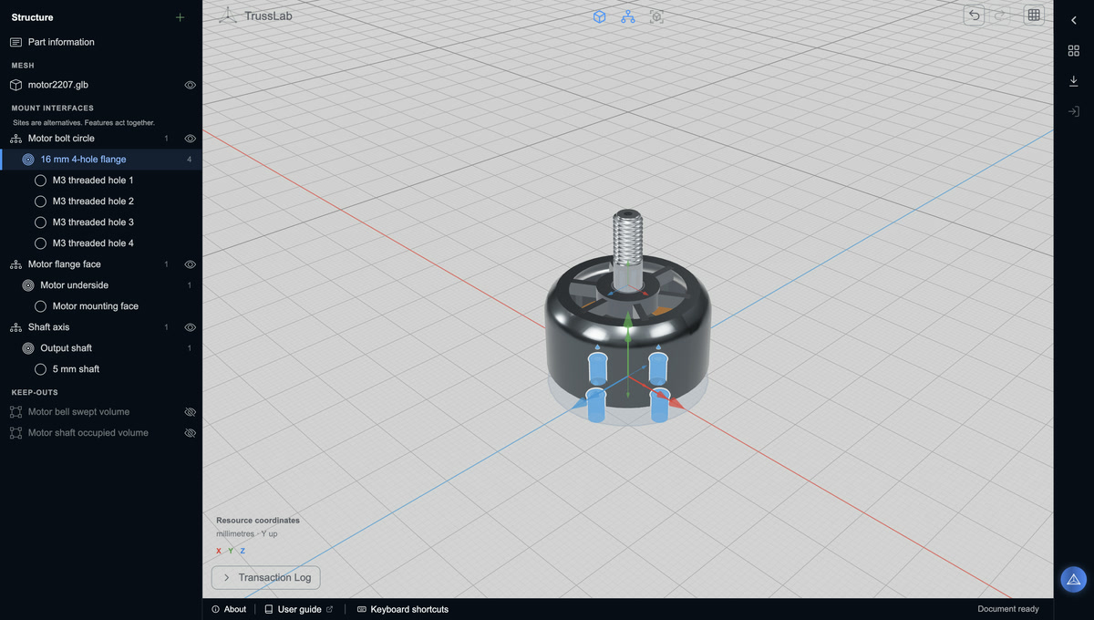
Open the mate-interface screenshot at full resolution.
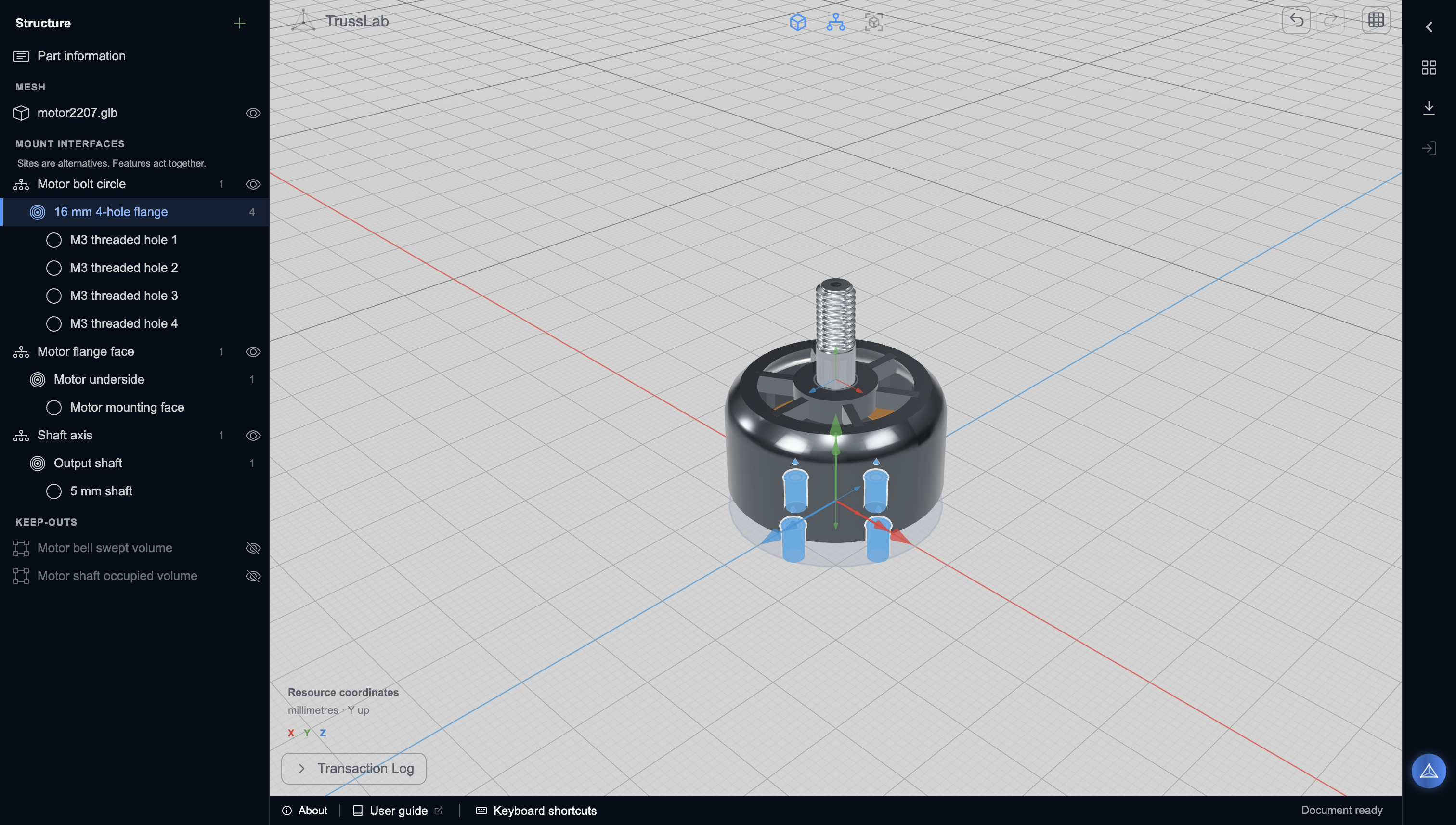
The four highlighted holes form one site's complete mounting pattern. The tree also shows separate flange-face and shaft-axis interfaces; those describe other mounting capabilities on the same fixed mesh.
Allow placement through this interface controls whether this part can be positioned through that interface. It can still receive another part when the option is off. Use a Required interface group when several interfaces must bind together. Shared site capacity lets alternative descriptions reserve the same physical mounting location instead of allowing duplicate hardware there.
Validate the definition by placing and mating the published part in a Frame. A compatible interface establishes placement; it does not prove physical fit or create printable geometry.
Add diagnostic keep-outs#
Choose Keep-out from the Add menu. Describe occupied space, access space, or a motion envelope with the numeric primitives and composition controls. Select whether it should check printable bodies, other foreign keep-outs, or both.
Keep-outs are diagnostic overlays. They never remove material from a printed fitting or enter STL/3MF geometry. Author the receiving hole or clearance in the Attachment Editor. Frame fit diagnostics are a separate inspection step; the Foreign Part Editor previews the authored volumes.
Publish and use the part#
Open Import/Export and choose Publish to Frame Editor, or use the publication badge. Publication makes a checked version available in this browser's local catalogue. It does not upload the part to a shared cloud library or add a built-in preset.
In a Frame, open Catalogue → Foreign parts and add the published part to that Frame's palette. Use + Add → Foreign part to place an instance. The catalogue manages available types; the Add menu creates instances.
Follow Foreign parts and assembly mates to choose Absolute, Mate, or On-guide placement. On-guide follows an existing node and virtual link with an offset and local rotation; it does not require an extra mate interface on the part. Try the linear-guide exercise for shared guides, reactive travel and fixed installation mates.
After revising and publishing a part, existing Frames keep their exact version. Use Use current exact release in the Frame catalogue to deliberately adopt the newer version and validate its existing placements.
Download geometry or share an editable design#
In Import/Export, GLB downloads the displayed mesh with its registered position, rotation, and scale. Editable TrussLab model also retains registration, interfaces, keep-outs, and part information so another user can edit the definition. Optional construction history includes the path leading to the displayed revision.
Use an editable model package to share one part and a workspace backup to preserve the complete workspace and retained alternatives. See Exporting and preparing a build.
Connected Pro agents can use the same authoring workflow through MCP. Read the MCP guide for editor scopes and publication.
Get occasional TrussLab updates, or send questions and build notes directly.
Subscribe to our newsletter