Designing the space that must stay empty
See why holes in an isolated part are insufficient when neighboring parts and connectors add material.
On this page
A hole in one body is only a local result#
Picture a sleeve with an opening for a tube. In isolation it looks correct: the tube can pass through the body. Now add another sleeve and a Hull connection to make a corner joint. New material can extend into that opening.
The local body subtraction describes the sleeve's own shape. Neighboring bodies and connector geometry also need to know which space they must preserve. This is why exported clearances are part of the reusable attachment contract.
Export the space other material must respect#
A clearance is subtractive geometry representing required empty space: a tube passage, a bolt bore, a receiving pocket, or space for an insert. Authoring that region as a local cut and exporting it as a clearance serve related but different purposes.
Within a connected printable component, applicable clearances are shared with the other connected bodies and applied to connection geometry. The design can add material around an interface while preserving the interface itself.
A node marked Clearance / keep-out is collected automatically for this purpose. There is no second export declaration to maintain. Its position in a local Difference and its clearance role express two different requirements: how to shape this body, and which space other connected material must leave empty.
Why not share every local subtractor automatically? A cut can simply shape one part. For example, a large cutting box might flatten one face; exporting that whole box as a keep-out could also remove wanted material from a neighboring part or the connector. Conversely, a tube's insertion path can require empty space beyond the sleeve's own body. The CSG operation alone cannot identify those assembly requirements.
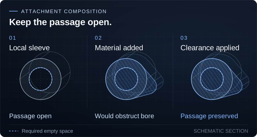
The drawing is schematic: pale outlines represent the sleeve, blue hatching shows added connector material, and the dashed blue circle marks required empty space. The middle stage shows where material would obstruct the bore before applying the shared clearance; the final stage preserves the passage. It illustrates the clearance rule rather than a particular attachment's exact export.
Watch two sleeves become one joint#
The recording starts with two physical tubes, each carrying an instance of the same Tube Sleeve type. The tubes are hidden to reveal the bores, then an Attachment Connection adds material between the sleeves. Inspect the resulting joint from both sides: the shared clearances preserve the tube passages through the added material.
Hiding the tubes makes the passages visible; it does not turn clearances off. Both sleeves use their normal clearance definitions throughout the recording.
Think in positive and subtractive geometry#
The useful composition is owning bodies plus connection geometry, with applicable shared clearances subtracted. Both parts of that definition matter.
A larger connector can increase material around a joint, but it cannot replace an incorrectly authored tube passage. A generous clearance can keep an interface open, but it can also remove needed wall material. Inspect the resulting component at realistic parameter values.
Sharing follows manufacturing connectivity#
Clearances are not a global cutter applied to every nearby object in the frame. Their propagation follows the connected component and the authored ownership rules.
Connections can form a chain through ports owned by the same body. Separate body-part branches on a multi-part attachment can remain independent. That matters for a clamp: joining one half to a sleeve should not silently make the other half part of that printed joint.
An assembly mate positions parts and makes dependents follow their owner. It does not establish this manufacturing connectivity. Use an Attachment Connection when printed bodies need to belong to a coordinated component.
Clearances enable reuse, with limits#
Each attachment declares its local shape and empty-space requirements. The frame decides how instances combine. A sleeve can therefore be reused at different corners without every neighboring part being authored specifically for that sleeve's hole layout.
That contract makes combination possible; it does not guarantee every combination is suitable. Host compatibility, parameter ranges, material continuity, remaining wall thickness, assembly order, and load direction still need inspection.
Check the final component#
Inspect the joint after its connections exist, then repeat after a meaningful size or angle change. Confirm that the tube passage stays open, fasteners remain accessible, insert pockets still fit, and enough material remains around every cut.
If a passage closes only after connecting, compare the attachment's local body subtraction with its exported clearance. If a whole feature disappears, inspect which connected clearance removes it. The connection reference defines component grouping in more detail.
Get occasional TrussLab updates, or send questions and build notes directly.
Subscribe to our newsletter