From a frame skeleton to a printable joint
Understand how design points, stock members, attachments, and connections become a buildable structure.
On this page
Begin with the structure#
Imagine two tubes meeting at a corner. The first design question is where their axes should run. Nodes and logical links describe that intent: points in space and the spans between them.
A logical span has no wall thickness, socket depth, or bolt access. It remains useful even when the physical details change. A Physical link describes the tube, rod, or profile manufactured along that reference span. Its section and terminal offsets determine the actual stock member.
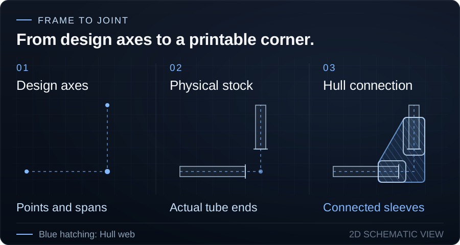
The diagram shows the design layers schematically. In the final 2D view, pale outlines identify the stock and its two sleeves; the blue hatched web shows Hull material joining the sleeve regions. It is not a dimensioned manufacturing model.
Stock members occupy space#
Two mathematical lines can meet at a point. Two real tubes meeting there can collide. Reconciliation is the explicit action that adjusts eligible Physical-link terminals to resolve their occupied space.
The terminal offsets determine where stock stops. Changing a frame dimension can require a fresh reconciliation pass. Dependent geometry updates automatically, but reconciliation runs when you choose Reconcile or Reconcile all links.
The result is ordinary model geometry and one reversible history step. Try it, inspect the endpoints, and undo if you want to revise the strategy. See Reconciliation for eligibility and constrained members.
Put a sleeve on each member#
An attachment supplies the local geometry that stock cannot: a sleeve, clamp, socket, foot, or mount. A Physical-link attachment knows its parent member and can use supported section dimensions to generate a fitting body.
At our corner, each sleeve is still an independent attachment instance. Its placement, parameters, and required empty space belong to it. The frame can reuse that same attachment type at another corner without designing another bracket from scratch.
Connect the sleeves into a joint#
An Attachment Connection selects ports on those attachments and determines how their owning bodies manufacture together. Hull can add bridging material between them. Shared clearances preserve the spaces each participating attachment needs.
The printable joint is derived from the placed bodies, the connection geometry, and the applicable clearances. The original attachments remain editable. Changing the corner angle or a supported member dimension regenerates the dependent geometry rather than replacing the design with a frozen mesh.
A joint can contain more than two attachments, and an attachment can have multiple manufactured bodies. The explicit connections determine which bodies belong together.
Inspect the layers independently#
Open the Triangle Frame narrated build. Pause as sleeves and corner connections appear. Identify the stock member, its sleeve, and the connection between sleeves before watching the next step.
Ask three questions: where is the structural reference, where does the real member end, and which printed bodies connect it to its neighbors? Separating those questions makes a complicated frame much easier to understand.
Get occasional TrussLab updates, or send questions and build notes directly.
Subscribe to our newsletter